

Technical Contents
Engineering Guide: Sheet Metal Product 3D Cad Modeling
Engineering Insight: Sheet Metal Product 3D CAD Modeling
In the realm of modern sheet metal fabrication, 3D CAD modeling is not merely a design tool—it is the foundation of precision engineering. At Wuxi Lead Precision Machinery, we recognize that the integrity, functionality, and manufacturability of a sheet metal component begin long before cutting or bending. They originate in the digital blueprint, where every dimension, tolerance, and feature is meticulously defined. Our decades of experience in high-stakes manufacturing for Olympic-standard equipment and military-grade systems have reinforced one undeniable truth: precision in 3D CAD modeling directly translates to performance in the physical product.
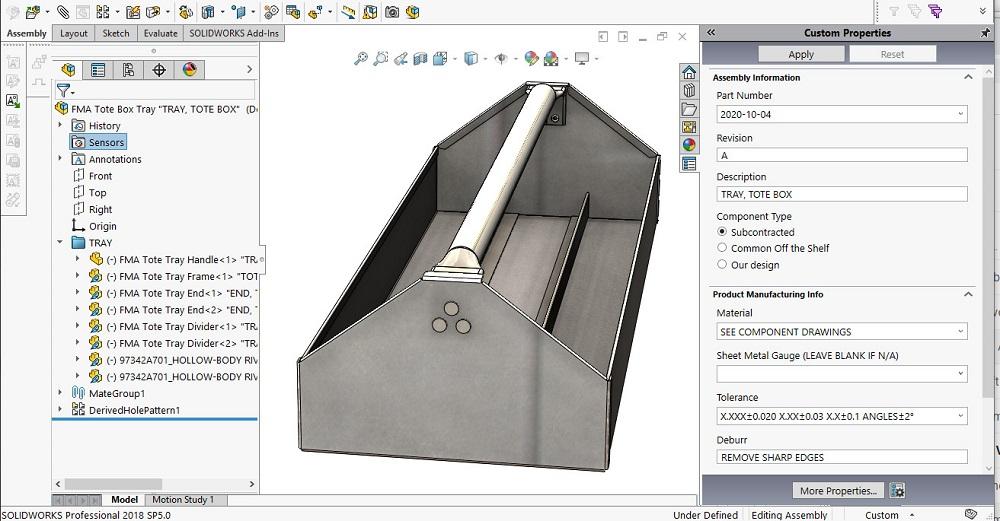
Sheet metal components used in aerospace, defense, medical, and advanced industrial applications demand exacting standards. A deviation of even 0.1 mm in a flange length or bend radius can compromise structural integrity, assembly fit, or system performance. Our engineering team employs industry-leading CAD platforms such as SolidWorks, Siemens NX, and Autodesk Inventor to develop parametric 3D models that reflect real-world manufacturing constraints. This includes precise k-factor calculations, bend allowance adjustments, and accurate flat pattern development—critical elements that ensure the final fabricated part matches the digital intent.
Beyond geometric accuracy, our 3D modeling process integrates Design for Manufacturability (DFM) principles from the outset. This proactive approach identifies potential fabrication challenges—such as tool access, minimum bend distances, or hole-to-edge clearances—before production begins. By simulating the entire fabrication workflow digitally, we minimize rework, reduce lead times, and enhance cost efficiency for our clients.
Wuxi Lead Precision Machinery’s involvement in mission-critical projects has honed our ability to deliver CAD models that meet the most rigorous specifications. Whether supporting the structural framework of Olympic timing systems or producing rugged enclosures for military electronics, our models are engineered to perform under extreme conditions. Each design undergoes a multi-stage validation process, including GD&T (Geometric Dimensioning and Tolerancing) analysis and cross-functional review by fabrication specialists.
We believe that superior manufacturing begins with superior modeling. Our commitment to precision in 3D CAD ensures that every sheet metal product we deliver is not only dimensionally accurate but also optimized for performance, durability, and seamless integration into complex assemblies.
Typical 3D CAD Modeling Specifications at Wuxi Lead Precision Machinery
| Parameter | Standard Specification |
|---|---|
| Modeling Software | SolidWorks, Siemens NX, Autodesk Inventor |
| File Formats Supported | STEP, IGES, Parasolid, DWG, DXF, PDF |
| Dimensional Tolerance | ±0.05 mm to ±0.1 mm (per ISO 2768) |
| Bend Allowance Accuracy | ±0.02 mm (based on material & thickness) |
| K-Factor Range | 0.30 – 0.50 (material-specific) |
| Surface Finish Specification | Ra 0.8 – 3.2 µm (as required) |
| GD&T Compliance | ASME Y14.5 or ISO 1101 |
| Design Validation Process | DFM, DFA, Flat Pattern Simulation |
Precision Specs & Tolerances
Technical Capabilities: Precision Sheet Metal Fabrication from CAD to Completion
Wuxi Lead Precision Machinery delivers advanced sheet metal fabrication solutions anchored in seamless integration between 3D CAD modeling and state-of-the-art manufacturing execution. Our engineering workflow begins with receiving or developing precise 3D CAD models, ensuring every design intent is fully captured and manufacturable from the outset. This critical digital foundation directly drives our production systems, eliminating interpretation errors and enabling rapid, accurate transition from virtual design to physical part. We specialize in transforming complex sheet metal geometries defined in models like SolidWorks, Creo, and AutoCAD into high-integrity components meeting the most demanding aerospace, medical, and industrial equipment specifications.
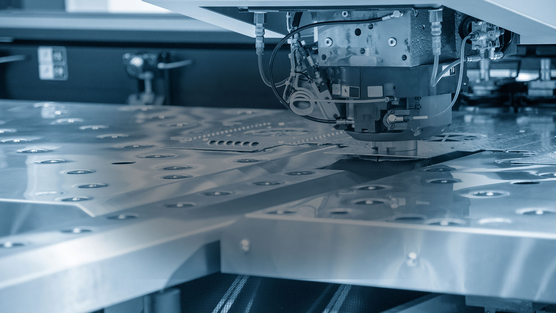
Central to our capability is a modern fleet of multi-axis CNC fabrication systems, including advanced 5-axis laser cutting and CNC turret punch-press technology. These platforms provide unparalleled flexibility for processing intricate contours, compound angles, and deep-drawn features impossible with conventional 3-axis machinery. The 5-axis capability allows simultaneous machining from multiple vectors, significantly reducing secondary operations and fixture changes. This translates to faster lead times, enhanced geometric complexity within single setups, and superior part consistency. Material utilization is optimized through intelligent nesting software directly linked to the CAD model, minimizing waste while maintaining structural integrity across diverse alloys including stainless steel, aluminum, and specialty composites.
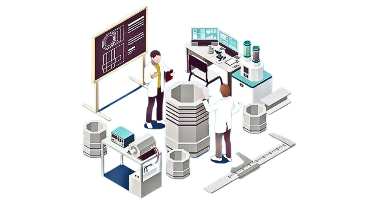
Rigorous quality control is non-negotiable. Every critical dimension and feature derived from the original 3D CAD model undergoes systematic verification using calibrated Coordinate Measuring Machines (CMM). Our CMM inspection protocols provide full traceability and dimensional accountability against both customer-supplied models and internal engineering drawings. This metrology-driven approach ensures parts conform precisely to specified tolerances throughout the production run, not just on initial samples. Statistical Process Control (SPC) data is actively monitored to maintain process stability and enable proactive adjustments, guaranteeing repeatability batch after batch.
The achievable precision for sheet metal components is fundamentally tied to material thickness and feature complexity. Wuxi Lead consistently meets or exceeds industry-standard tolerance expectations, as demonstrated in the following specifications:
| Material Thickness Range | Linear Dimension Tolerance | Hole Position Tolerance | Bend Angle Tolerance | Bend Radius Tolerance |
|---|---|---|---|---|
| 0.5 mm – 1.0 mm | ±0.05 mm | ±0.05 mm | ±0.5° | ±0.1 mm |
| 1.0 mm – 3.0 mm | ±0.08 mm | ±0.08 mm | ±0.75° | ±0.15 mm |
| 3.0 mm – 6.0 mm | ±0.10 mm | ±0.10 mm | ±1.0° | ±0.20 mm |
| > 6.0 mm | ±0.15 mm | ±0.15 mm | ±1.5° | ±0.25 mm |
These tolerances are maintained under controlled ISO 9001 environmental conditions and validated through our CMM inspection regime. Wuxi Lead Precision Machinery provides the complete technical capability spectrum—from sophisticated 3D CAD model interpretation through precision 5-axis fabrication to certified dimensional verification—ensuring your sheet metal components meet the highest standards of accuracy and reliability required for mission-critical applications.
Material & Finish Options

Material Selection for Sheet Metal Product 3D CAD Modeling
Selecting the appropriate material during the 3D CAD modeling phase is critical to ensuring manufacturability, performance, and cost-efficiency in sheet metal fabrication. At Wuxi Lead Precision Machinery, we emphasize early-stage material integration into the design process to align engineering intent with production reality. The three most widely used metals in precision sheet metal applications—aluminum, steel, and titanium—each offer unique mechanical and chemical properties that influence design decisions, tooling requirements, and finishing options.
Aluminum is a preferred choice for lightweight, corrosion-resistant components in aerospace, electronics, and transportation sectors. Its high strength-to-weight ratio and excellent thermal conductivity make it ideal for heat sinks, enclosures, and structural frames. During 3D CAD modeling, designers must account for aluminum’s lower elastic modulus compared to steel, which may affect bend allowances and springback behavior. Grade 5052 and 6061 are commonly used in sheet form due to their weldability and formability.
Steel remains the backbone of industrial sheet metal fabrication, with carbon steel (e.g., AISI 1008–1020) offering high tensile strength and cost-effective machinability. It is widely used in machinery enclosures, chassis, and support structures. However, its susceptibility to oxidation necessitates protective finishes. Stainless steel grades such as 304 and 316 provide inherent corrosion resistance and are suitable for medical, food processing, and marine environments. When modeling with steel, designers should consider higher tool wear and springback compensation in bending operations.
Titanium, though significantly more expensive, delivers exceptional strength-to-density performance and resistance to extreme temperatures and corrosive environments. It is typically reserved for high-performance aerospace, defense, and medical implant applications. Its low thermal conductivity and high reactivity require specialized fabrication techniques, which must be reflected in the CAD model’s tolerance specifications and feature geometry.
Surface finish selection begins at the design stage. Anodizing is a key post-processing method for aluminum, enhancing wear resistance and enabling color coding or branding. Type II (sulfuric acid) and Type III (hardcoat) anodizing offer varying thickness and durability levels. CAD models must include callouts for anodizing zones, masking requirements, and tolerance allowances, as the process adds dimensional growth (typically 0.0002–0.001 in per surface). For steel, alternatives such as powder coating or passivation are more common, while titanium often undergoes anodizing for aesthetic or insulative purposes, though not for wear enhancement.
Below is a comparative overview of key material properties relevant to sheet metal design and fabrication.
| Material | Typical Grades | Density (g/cm³) | Tensile Strength (MPa) | Common Sheet Thickness Range (mm) | Key Applications |
|---|---|---|---|---|---|
| Aluminum | 5052, 6061 | 2.7 | 200–310 | 0.5–6.0 | Enclosures, heat sinks, frames |
| Carbon Steel | AISI 1008, 1010 | 7.85 | 340–420 | 0.8–12.0 | Industrial housings, brackets |
| Stainless Steel | 304, 316 | 8.0 | 505–620 | 0.5–10.0 | Medical, food processing, marine |
| Titanium | Grade 2, Grade 5 | 4.5 | 345–860 | 0.8–5.0 | Aerospace, defense, medical |
Integrating material and finish specifications directly into 3D CAD models ensures seamless transition from design to fabrication, minimizing rework and accelerating time to market.
Manufacturing Process & QC
Sheet Metal Product 3D CAD Modeling: The Zero Defect Production Process
At Wuxi Lead Precision Machinery, our sheet metal fabrication process is engineered for absolute precision from initial concept to final shipment. We implement a rigorously controlled workflow—Design, Prototyping, Mass Production—where Zero Defects is not a goal but a non-negotiable standard. This integrated approach ensures manufacturability, minimizes waste, and guarantees end-product integrity for demanding industrial applications.
The Design phase begins with deep collaboration between our engineering team and the client. We utilize advanced 3D CAD software (SolidWorks, Siemens NX) to model components with strict adherence to Design for Manufacturability (DFM) principles specific to sheet metal. Critical parameters—material grade and thickness, bend radii, K-factors, and tooling constraints—are embedded directly into the model. This eliminates theoretical designs that fail on the shop floor. Every flange, cutout, and emboss is validated against our press brake tooling library and laser cutting capabilities during modeling, ensuring the digital file is production-ready. Material selection considers not only mechanical properties but also formability and post-processing requirements like welding or finishing, preventing downstream failures.
Prototyping transforms the validated CAD model into a physical test article under controlled conditions. We employ rapid prototyping methods—CNC laser cutting for flat patterns followed by precision press brake forming—to produce functional prototypes matching production intent. These prototypes undergo exhaustive metrology using Coordinate Measuring Machines (CMM) and optical comparators. Critical dimensions, geometric tolerances, and assembly fit are verified against the original CAD data. This phase identifies subtle issues like springback effects or interference that simulation alone might miss. The prototype serves as the definitive benchmark for mass production setup.
Following prototype approval, mass production commences under our Zero Defects management system. Each stage incorporates Statistical Process Control (SPC) with real-time monitoring of key parameters: laser power stability, press brake angle repeatability, and material feed accuracy. Every component is traceable via serialized part numbers linked to machine logs and inspection records. Automated vision systems perform 100% inspection on critical features during forming and assembly. Any deviation beyond predefined control limits triggers immediate process correction, not just part rejection. This closed-loop system, combined with operator certification and rigorous first-article inspection protocols, ensures consistency across volumes from 10 to 100,000+ units.
Prototype validation metrics are strictly quantified to ensure production readiness:
| Validation Parameter | Target Tolerance | Measurement Method | Acceptance Criteria |
|---|---|---|---|
| Overall Flatness | ≤ ±0.1mm | Granite Surface Plate + Dial Gauge | 100% of points within spec |
| Critical Hole Position | ±0.05mm | CMM | Max deviation ≤ spec |
| Bend Angle Consistency | ±0.5° | Precision Angle Gauge | All bends within range |
| Edge Condition | Burr Height ≤ 0.05mm | Optical Microscope | No sharp edges or excessive burr |
This seamless transition from precise digital definition through physical validation to controlled high-volume execution is the core of Wuxi Lead’s Zero Defects commitment. We deliver sheet metal components that meet exacting global standards, eliminating rework and accelerating time-to-market for our clients.
Why Choose Wuxi Lead Precision
Partner with Lead Precision for Unmatched Expertise in Sheet Metal Product 3D CAD Modeling
At Wuxi Lead Precision Machinery, we understand that precision, speed, and reliability are non-negotiable in modern sheet metal fabrication. As a trusted leader in high-end manufacturing solutions based in China, we specialize in transforming conceptual designs into production-ready 3D CAD models tailored to your exact engineering and manufacturing requirements. Our team of certified mechanical engineers and CAD specialists leverages the latest in SolidWorks, Autodesk Inventor, and Siemens NX software to deliver intelligent, manufacturable models that streamline prototyping, reduce material waste, and accelerate time-to-market.
When you partner with Lead Precision, you gain more than a service provider—you gain a strategic collaborator. We don’t just model parts; we optimize them. Every 3D CAD model we produce is designed with manufacturability in mind, incorporating critical considerations such as bend allowances, k-factor accuracy, tool clearance, and assembly fit. Our deep integration with our in-house CNC punching, laser cutting, bending, and welding operations ensures that your digital model translates seamlessly into physical reality—without costly redesigns or production delays.
Our clients across the industrial automation, renewable energy, telecommunications, and transportation sectors rely on our 3D CAD modeling services to bridge the gap between innovation and industrial scalability. Whether you’re scaling from prototype to production or require full design validation and DFM analysis, our engineering team collaborates closely with yours to ensure every dimension, tolerance, and feature meets your functional and regulatory standards.
We support a wide range of file formats including STEP, IGES, Parasolid, and native CAD files, ensuring seamless integration with your existing design workflows. All intellectual property is protected under strict NDA agreements, and our quality management system is ISO 9001:2015 certified, guaranteeing consistency and traceability across every project.
| Specification | Detail |
|---|---|
| Supported CAD Software | SolidWorks, Autodesk Inventor, Siemens NX, AutoCAD |
| Output Formats | STEP, IGES, Parasolid, DWG, DXF, PDF |
| Tolerance Standards | ISO 2768, GD&T (ASME Y14.5) |
| Lead Time (Standard) | 2–5 business days per model |
| File Compatibility | Native and cross-platform interoperability |
| Quality Certification | ISO 9001:2015 |
| IP Protection | Full NDA coverage, secure data handling |
Contact us today to discuss your next sheet metal fabrication project. Send your sketches, concepts, or existing models to [email protected] and let our engineering team deliver precision 3D CAD models built for manufacturing excellence. Partner with Wuxi Lead Precision Machinery—where design meets industrial precision.
⚙️ Precision Cost Estimator
Estimate relative manufacturing effort based on tolerance.