

Technical Contents
Engineering Guide: Bend Radius Chart For Sheet Metal
Engineering Insight: The Critical Role of Bend Radius in Sheet Metal Fabrication
In high-precision sheet metal fabrication, the bend radius is far more than a dimensional specification—it is a foundational element that determines the structural integrity, dimensional accuracy, and functional performance of a finished component. At Wuxi Lead Precision Machinery, we understand that even the slightest deviation in bend radius can lead to material failure, increased springback, or fitment issues in final assembly. This is especially critical in industries where performance under stress is non-negotiable—such as aerospace, defense, and high-end industrial equipment.
The bend radius refers to the inside radius formed when sheet metal is bent. It must be carefully calculated based on material type, thickness, grain direction, and tooling geometry. An improperly selected radius can result in cracking at the bend line, deformation of adjacent features, or compromised fatigue resistance. In military-grade enclosures or structural components used in Olympic-standard equipment, such flaws are unacceptable. Our engineering team at Lead Precision has consistently delivered components meeting MIL-STD and ISO 9001 standards, where precision in bend radius directly correlates with mission-critical reliability.
One of the most common misconceptions is that a smaller bend radius is always better. In reality, forcing a bend radius below the material’s minimum capability induces excessive tensile stress on the outer fiber of the bend, leading to microfractures. Conversely, an overly large radius may interfere with part fit or assembly requirements. The optimal bend radius ensures uniform material flow, minimizes springback, and maintains cross-sectional integrity. This balance is achieved through advanced simulation software, precision press brake tooling, and decades of hands-on experience.
At Wuxi Lead, our fabrication processes are backed by rigorous material testing and real-time feedback systems on our CNC press brakes. This allows us to maintain bend radius tolerances within ±0.2 mm, even across complex multi-bend geometries. Our work on precision frames for Olympic timing systems and ruggedized housings for military communication units underscores our commitment to dimensional perfection.
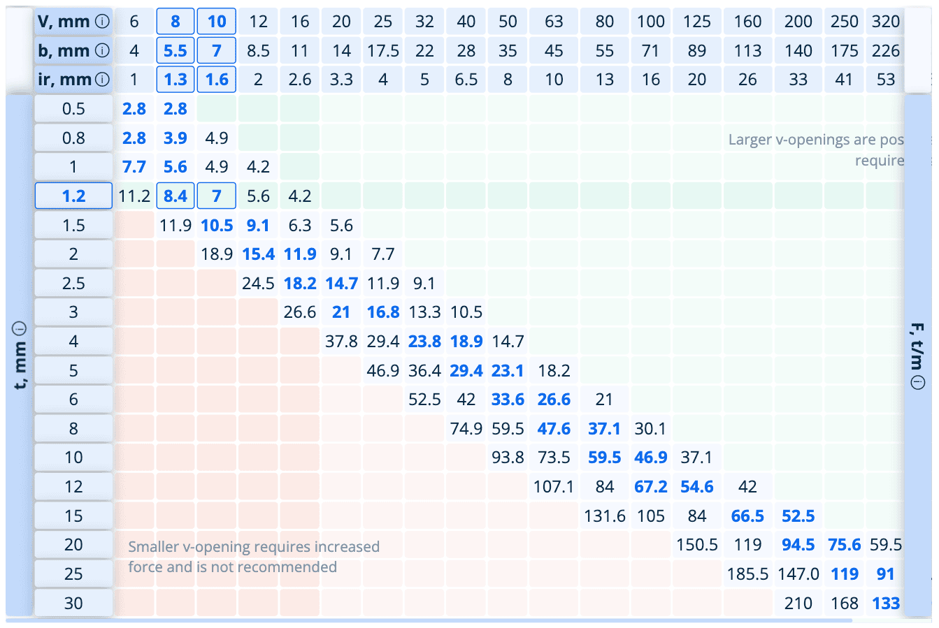
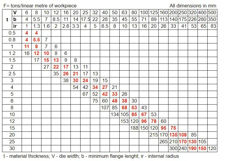
Below is a reference chart outlining recommended minimum bend radii for common sheet metal materials at standard thicknesses. These values assume sharp tooling and proper grain orientation, and are derived from our in-house testing protocols.
| Material | Thickness (mm) | Minimum Internal Bend Radius (mm) | Notes |
|---|---|---|---|
| Cold Rolled Steel | 0.8 | 0.5 | Standard tooling, grain parallel |
| Cold Rolled Steel | 1.5 | 1.0 | Optimal for structural brackets |
| Cold Rolled Steel | 3.0 | 2.5 | Requires high-tonnage press brake |
| Aluminum 5052 | 1.0 | 1.0 | Slight cracking risk below 1.0 mm |
| Aluminum 6061 | 2.0 | 2.5 | Heat-treated condition; higher springback |
| Stainless Steel 304 | 1.2 | 1.2 | High work-hardening rate |
| Stainless Steel 304 | 2.5 | 2.5 | Requires polished tooling to prevent galling |
Precision in bend radius is not an optional parameter—it is a non-negotiable standard in high-end manufacturing. At Wuxi Lead Precision Machinery, we combine engineering rigor with proven field experience to ensure every bend meets the highest benchmarks of quality and performance.
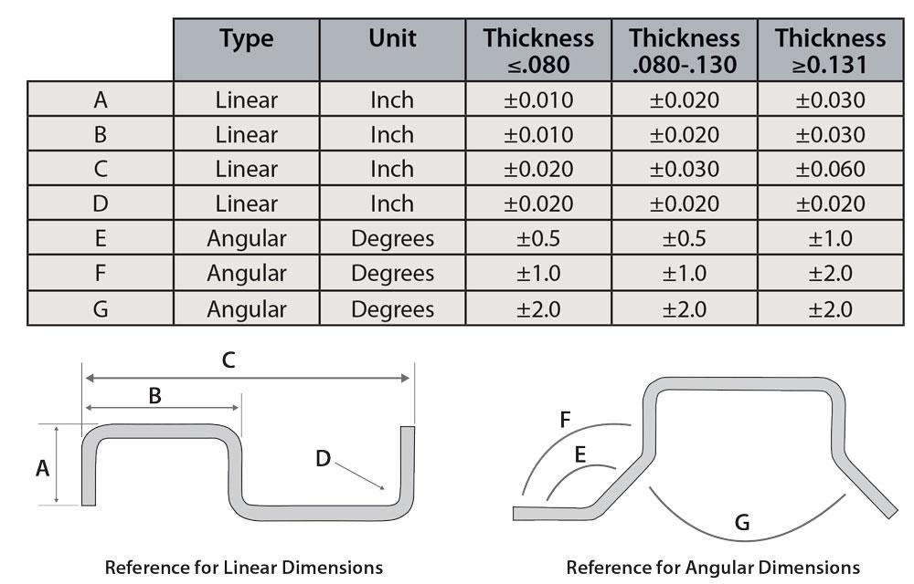
Precision Specs & Tolerances
Technical Capabilities: Precision Sheet Metal Bending at Wuxi Lead Precision Machinery
Achieving optimal bend radii in sheet metal fabrication is fundamental to part functionality, structural integrity, and assembly compatibility. At Wuxi Lead Precision Machinery, we address this critical parameter through advanced engineering controls and state-of-the-art equipment, ensuring consistent adherence to your design specifications. Material behavior during bending—impacted by thickness, alloy, grain direction, and tooling geometry—demands precise process calibration. Our methodology eliminates guesswork by integrating material science with real-time machine feedback, directly translating engineering intent into flawless physical components.
Central to our capability is a dedicated fleet of 5-axis CNC press brakes, featuring automatic tool changers and laser-guided backgauging systems. These machines operate under closed-loop control, dynamically adjusting tonnage and stroke depth to compensate for material springback and thickness variance. Unlike conventional 3-axis systems, our 5-axis platforms enable simultaneous multi-plane bending, critical for complex geometries requiring tight internal radii without secondary operations. Each brake is calibrated to ±0.01mm positional accuracy and utilizes segmented tooling libraries optimized for stainless steel, aluminum, and carbon steel alloys. This ensures minimal distortion and repeatable bend angles across production runs, even for radii as tight as 0.5x material thickness in high-strength alloys.
Quality verification is non-negotiable. Every bent component undergoes first-article and in-process inspection via Zeiss O-INSPECT 544 multisensor CMMs, providing traceable measurement of bend radius, angle deviation, and flatness to ISO 2768-mK standards. Our inspection protocols validate radius conformity against the ASME Y14.2 bend chart guidelines, with data logged for full production lot traceability. This closed-loop quality system—integrating machine telemetry, CMM results, and SPC analysis—guarantees that dimensional tolerances are maintained within defined limits, reducing scrap rates and accelerating time-to-assembly for clients.
The following table details achievable bend radius tolerances across common materials and thicknesses under our controlled process parameters:
| Material | Thickness Range (mm) | Minimum Achievable Radius | Angular Tolerance | Radius Tolerance |
|---|---|---|---|---|
| 304 Stainless Steel | 0.5 – 3.0 | 0.5t | ±0.5° | ±0.1mm |
| 6061-T6 Aluminum | 0.8 – 4.0 | 0.8t | ±0.3° | ±0.05mm |
| Cold Roll Steel | 0.6 – 6.0 | 0.6t | ±0.4° | ±0.1mm |
| Brass (C260) | 1.0 – 3.0 | 1.0t | ±0.6° | ±0.15mm |
Our technical approach transforms bend radius from a fabrication constraint into a controlled engineering variable. By leveraging 5-axis CNC precision, material-specific process algorithms, and CMM-validated quality gates, Wuxi Lead delivers components where form, fit, and function align exactly with your design requirements. This capability directly supports reduced prototyping cycles, minimized rework, and accelerated production ramp-up for high-value assemblies in aerospace, medical, and industrial equipment sectors. Partner with us to convert complex sheet metal designs into reality—without compromise.
Material & Finish Options
Material Selection for Optimal Bend Radius in Sheet Metal Fabrication
Selecting the appropriate material is critical when designing sheet metal components, particularly when considering the minimum bend radius. The bend radius directly influences the structural integrity, manufacturability, and final performance of the part. At Wuxi Lead Precision Machinery, we emphasize material-specific behavior during bending operations to prevent cracking, deformation, or failure. The most commonly used materials in high-precision fabrication—aluminum, steel, and titanium—each exhibit distinct mechanical properties that affect bendability and required tooling.
Aluminum is widely favored for its lightweight nature, corrosion resistance, and excellent formability. However, its relatively low ductility in certain alloys necessitates careful consideration of the minimum bend radius. For example, 5052-H32 and 6061-T6 aluminum grades require different bend allowances due to variations in tensile strength and elongation. When bending aluminum, maintaining a radius equal to or greater than the material thickness is typically recommended to avoid surface fractures, especially in heat-treated conditions.
Steel remains the backbone of industrial fabrication due to its strength, durability, and cost-effectiveness. Low-carbon steel (such as ASTM A36 or SPCC) offers superior ductility, allowing for tighter bend radii—often as low as 0.5 times the material thickness. On the other hand, high-strength steels and hardened alloys may require larger radii to prevent cracking along the bend line. Proper grain direction alignment during bending further enhances performance, particularly in load-bearing applications.
Titanium, though less common due to its cost and machining complexity, is essential in aerospace and medical industries where strength-to-density ratios and corrosion resistance are paramount. Titanium’s high strength and low elasticity demand larger minimum bend radii—typically two to three times the material thickness—to mitigate stress concentration and avoid microfractures. Springback is also more pronounced in titanium, requiring overbending compensation in tool design.
Surface finish selection, particularly anodizing for aluminum, must be considered during material and bend radius planning. Anodized layers are brittle and prone to cracking when subjected to tight bends. Therefore, anodizing should ideally be performed post-forming. If pre-anodized material must be used, a larger bend radius is mandatory to preserve coating integrity.
The following table summarizes key material properties and recommended bend radius guidelines for precision sheet metal work.
| Material | Typical Grades | Tensile Strength (MPa) | Elongation (%) | Recommended Minimum Bend Radius (as multiple of thickness) |
|---|---|---|---|---|
| Aluminum | 5052-H32, 6061-T6 | 200 – 310 | 12 – 25 | 1.0 – 1.5 |
| Low-Carbon Steel | SPCC, ASTM A36 | 360 – 500 | 30 – 40 | 0.5 – 1.0 |
| High-Strength Steel | Q345, SAE 4140 | 550 – 900 | 15 – 20 | 1.5 – 2.0 |
| Titanium | Grade 2, Grade 5 (Ti-6Al-4V) | 345 – 900 | 15 – 20 | 2.0 – 3.0 |
Understanding these material behaviors ensures reliable forming, reduces scrap rates, and enhances final product quality. At Wuxi Lead Precision Machinery, we integrate material science with advanced CNC press brake technology to deliver precision sheet metal solutions tailored to your engineering requirements.
Manufacturing Process & QC
Precision Bending Begins with Accurate Bend Radius Definition
Achieving flawless sheet metal components demands rigorous adherence to material-specific bend radius parameters from the earliest design phase. An undersized internal radius induces surface cracks, material thinning, and structural weakness, while an oversized radius compromises dimensional accuracy and assembly fit. At Wuxi Lead Precision Machinery, our engineering team integrates validated bend radius charts directly into CAD models during design, ensuring manufacturability before prototyping begins. This proactive approach eliminates costly rework by aligning theoretical geometry with physical material behavior under stress.
Prototyping Validates the Process, Not Just the Part
Design-stage radius specifications undergo empirical verification through physical prototyping. We execute test bends using production-intent tooling and press brakes, measuring springback, edge quality, and internal stress via coordinate measuring machines (CMM) and optical comparators. Finite element analysis (FEA) simulations cross-verify prototype results, identifying potential micro-fractures invisible to the naked eye. Only when the prototype consistently achieves the target radius without deformation or cracking does the process advance. This phase is non-negotiable for Zero Defects; it confirms that the bend chart’s theoretical values translate to real-world repeatability under controlled shop-floor conditions.
Mass Production Executes with Closed-Loop Control
Transitioning to high-volume production requires embedding bend radius integrity into every operational layer. Our CNC press brakes utilize real-time feedback systems that automatically adjust tonnage and stroke depth based on material batch certifications and temperature fluctuations. Statistical process control (SPC) charts monitor radius deviations across every 50th part, triggering immediate tooling recalibration if trends approach tolerance limits. Tooling wear is tracked via laser micrometers, with inserts replaced proactively before degradation affects radius consistency. Crucially, operators reference Wuxi Lead’s updated internal bend radius specifications—not generic industry charts—ensuring alignment with our validated material databases.
Material-Specific Minimum Internal Radius Specifications
The following table reflects Wuxi Lead’s production-tested minimum internal radii for common materials. These values assume standard grain direction and room-temperature forming; adjustments apply for specialized alloys or extreme environments.
| Material | Thickness Range (mm) | Min Internal Radius (mm) | Critical Notes |
|---|---|---|---|
| Aluminum 5052-H32 | 0.8 – 3.0 | 0.8 × Thickness | Grain direction perpendicular to bend essential |
| Cold Rolled Steel | 1.0 – 4.0 | 0.4 × Thickness | Verify yield strength batch certification |
| Stainless 304 | 1.5 – 6.0 | 1.0 × Thickness | Higher springback requires +15% overbend |
Zero Defects is a System, Not a Goal
Bend radius integrity permeates our entire production ecosystem—from design rule libraries to tooling maintenance logs. By treating the bend radius chart as a dynamic, process-controlled variable rather than a static reference, Wuxi Lead achieves sub-0.1mm radius repeatability across 10,000+ part runs. This methodology transforms theoretical tolerances into guaranteed outcomes, eliminating bending-related failures before they reach your assembly line. Partner with us to convert precision specifications into defect-free deliverables.
Why Choose Wuxi Lead Precision
Partner with Wuxi Lead Precision Machinery for Expert Guidance in Sheet Metal Fabrication
When precision, consistency, and reliability define your manufacturing standards, partnering with a trusted leader in sheet metal fabrication becomes essential. At Wuxi Lead Precision Machinery, we specialize in delivering high-accuracy bending solutions tailored to your engineering requirements. Our expertise extends beyond machinery—we provide actionable technical insights, including precise bend radius recommendations critical to achieving optimal part performance and structural integrity.
Understanding the correct bend radius is fundamental in sheet metal design. Too tight a radius risks cracking or material deformation; too large a radius compromises dimensional accuracy and fit. Our engineering team leverages decades of hands-on experience to help clients determine the ideal bend radius based on material type, thickness, and application demands. Whether you’re working with mild steel, stainless steel, aluminum, or copper alloys, our support ensures your designs translate flawlessly from prototype to production.
We recognize that every fabrication challenge is unique. That’s why we offer personalized consultation services to guide you through material selection, tooling setup, and process optimization. Our bend radius charts are not generic references—they are engineered recommendations derived from real-world production data and validated across thousands of parts. When you partner with us, you gain access to technical documentation that aligns with international standards while being fine-tuned for your specific manufacturing environment.
Our state-of-the-art CNC press brakes, combined with advanced simulation software, allow us to replicate and verify bend behavior before any material is cut. This proactive approach minimizes waste, reduces setup time, and ensures repeatable quality across batches. From low-volume prototypes to high-volume production runs, our processes are built to scale without compromising precision.
Below is a representative bend radius reference table based on common materials and thicknesses processed on our equipment. These values serve as a starting point—final parameters are always adjusted according to material batch, grain direction, and tooling condition.
| Material | Thickness (mm) | Minimum Bend Radius (mm) | Tool Width (V) | K-Factor |
|---|---|---|---|---|
| Mild Steel | 1.0 | 0.5 | 6 | 0.42 |
| Mild Steel | 2.0 | 1.0 | 12 | 0.45 |
| Stainless Steel 304 | 1.5 | 1.0 | 10 | 0.48 |
| Aluminum 5052 | 1.0 | 0.8 | 8 | 0.38 |
| Copper C110 | 0.8 | 0.6 | 6 | 0.40 |
These specifications reflect standard air bending conditions using precision tooling. Actual values may vary depending on machine calibration and material properties. For mission-critical applications, we recommend direct consultation with our engineering team to validate parameters.
Let Wuxi Lead Precision Machinery be your technical partner in achieving flawless sheet metal fabrication. Contact us today at [email protected] to request a detailed bend radius chart, discuss your project requirements, or schedule a technical review with our fabrication specialists. Precision begins with the right partnership—start the conversation now.
⚙️ Precision Cost Estimator
Estimate relative manufacturing effort based on tolerance.